Engineering sample
Why do truss bridges use so many triangles?
Why truss bridges use triangles
Trace how a triangular truss keeps its shape and carries bridge loads through tension and compression.
Reviewed 2026-08-10 · 4 minute read
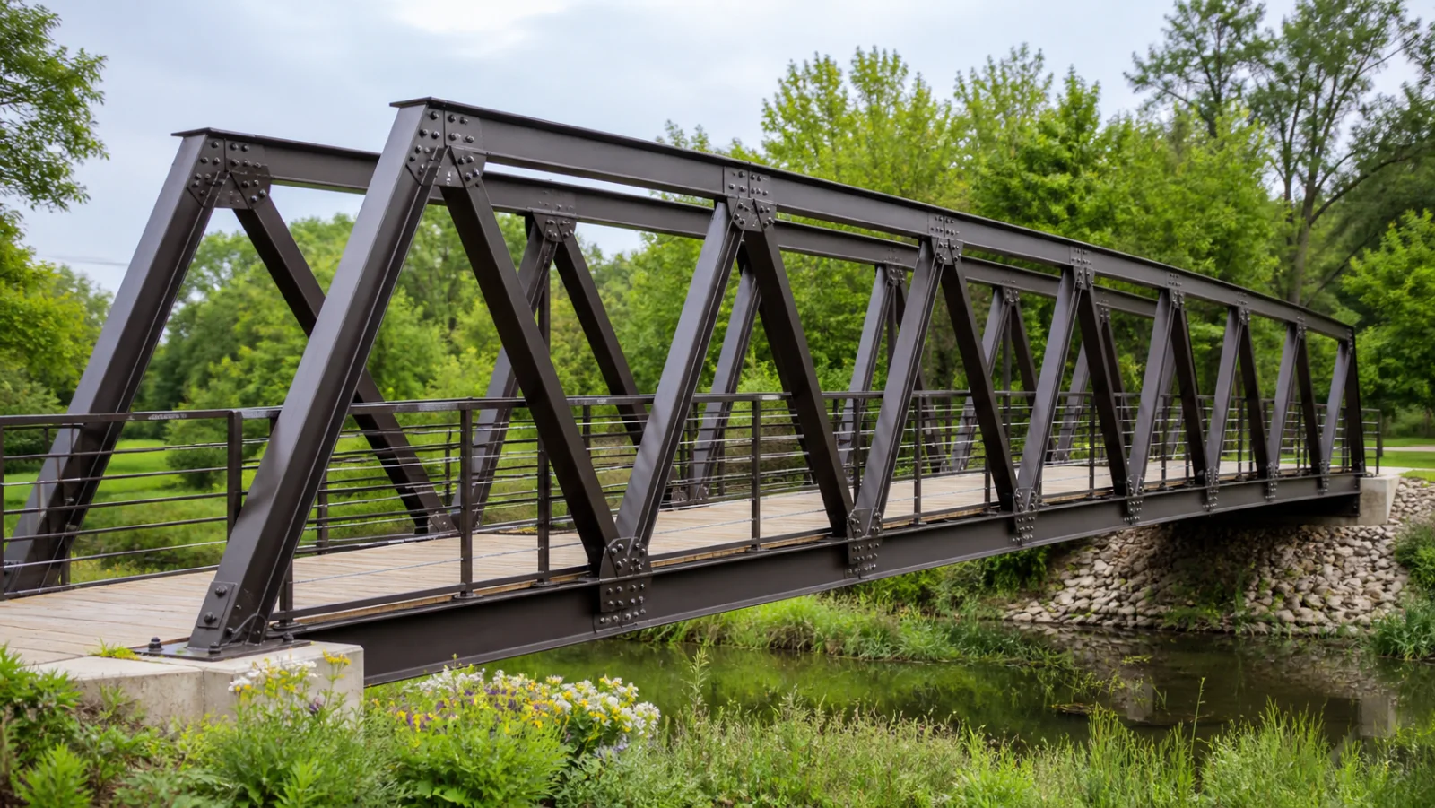
Core principle
A triangle cannot change shape without changing the length of one of its sides. In an ideal truss, that geometric stability lets loads travel through slender members mainly as axial tension or compression instead of large bending forces.
What the image shows
- The side structure repeats triangular bays instead of relying on large four-sided frames.
- Diagonal, vertical, and horizontal members meet at distinct joints along the bridge.
- The deck spans between supports while the truss rises above it to create a deeper load-carrying structure.
Mechanism and evidence
- People, the deck, and the bridge's own weight create downward loads. Engineers model many of those loads as entering the truss at its joints, called panel points.
- A four-sided frame can rack into a slanted shape while its side lengths stay almost unchanged. Adding a diagonal divides it into triangles, so a shape change must stretch or shorten a member.
- Each truss member then helps carry the load by pulling in tension or pushing in compression. Which member does which depends on the truss geometry, supports, and exact loading position.
- The connected members deliver the forces to the bridge supports, whose reactions transfer the load into abutments and the ground.
Useful relationships
\sigma = \frac{F}{A}Axial stress is the member force divided by its cross-sectional area. It helps an engineer compare the internal force with what the material can safely carry.
Variables that could change it
- Bridge span and truss depth
- Member cross-sectional area and steel grade
- Connection stiffness and joint details
- Position and size of live loads
- Wind, vibration, corrosion, and fatigue
- Buckling resistance of compressed members
Limits in this image
- This is a generated teaching illustration, not a photograph or engineering inspection of a specific bridge.
- The direction and magnitude of force in each member cannot be determined from appearance alone.
Sources and review
- Covered Bridge Manual, Chapter 2: Types of Covered Bridges — U.S. Federal Highway Administration
- Bridge Geometry Manual — U.S. Federal Highway Administration
- Stress, Strain, and Elastic Modulus — OpenStax
Reviewed by SciLens source review on 2026-08-10. Suggest a correction.